
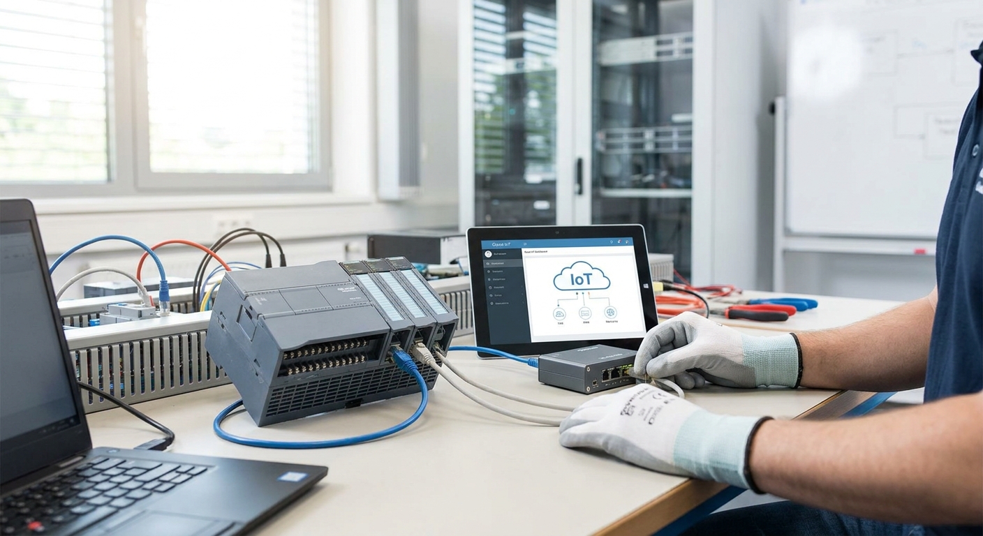
Most PLCs on a factory floor still speak Modbus, and most cloud dashboards speak MQTT or REST. Bridging the two takes a gateway, not a rewrite of your automation layer — here's the exact path from a Modbus RTU or TCP PLC to a live cloud dashboard in 2026.
- A Modbus-to-MQTT gateway is the fastest way to connect modbus plcs to a cloud iot dashboard without touching PLC firmware.
- Poll intervals of 5-30 seconds cover most PLC use cases; anything faster strains RTU serial links.
- Kilo Cloud's rules engine can trigger alarms directly off Modbus register values once they land as MQTT topics.
- Buy a protocol-agnostic gateway over a single-vendor box if you run more than one PLC brand on site.
Why this matters
PLCs generate register data no one outside the control room ever sees. That's fine until a compressor trips at 2 a.m. or a tank overfills on a shift with nobody watching the HMI.
Getting that register data into a cloud dashboard means facilities and ops teams get alerts on their phone instead of finding out from a shutdown log the next morning. It also means one dashboard across sites, instead of a different HMI screen at every location.
The hard part isn't the cloud side. It's picking the right gateway and mapping registers correctly the first time, because a wrong data type on a 16-bit register turns a normal temperature reading into garbage.
What you'll need
- A Modbus RTU (RS-485) or Modbus TCP-capable PLC — most Allen-Bradley, Siemens, and Schneider units built after the early 2000s support one or both
- A Modbus-to-MQTT (or Modbus-to-REST) gateway — hardware unit or software running on an edge PC/Raspberry Pi
- The PLC's register map: addresses, data types (int16, float32, etc.), and register-to-tag names from your integrator or PLC documentation
- Network access from the gateway to both the PLC (serial or Ethernet) and the internet (outbound MQTT/HTTPS, typically port 1883/8883)
- A cloud IoT platform account with MQTT broker access and a rules engine for alarms — this is where a multi-protocol gateway setup earns its cost if you're running more than a single PLC model
- 2-4 hours for first-time setup on a single PLC; add 30-60 minutes per additional device once the template is built
The steps
1. Pull the register map before you touch hardware
Every Modbus device ships with a register table — holding registers, input registers, coils, discrete inputs — and each one maps to a physical value like temperature, pressure, or run status.
Write down the address, register type, data type, and scaling factor for every point you want in the cloud. A temperature register stored as int16 with a scale of 0.1 means a raw value of 235 is actually 23.5°C — miss that scaling factor and your dashboard shows readings 10x too high.
Common mistake: assuming all registers use the same byte order. Big-endian and little-endian mismatches are the number one cause of nonsense values on a first Modbus integration.
2. Wire and configure the gateway
For Modbus RTU, connect the gateway's RS-485 terminals to the PLC's serial port, matching baud rate, parity, and stop bits exactly — a mismatch here means zero communication, not partial data. For Modbus TCP, it's just an Ethernet connection and the PLC's IP address plus port 502.
Set the gateway to poll each register on a fixed interval. 5-30 seconds works for most temperature, pressure, and status monitoring; go faster only if you're catching fast transients like vibration spikes, and expect serial bus load to climb accordingly.
Expected outcome: the gateway's local diagnostic screen or log shows live register values updating on schedule, before any cloud connection exists.
3. Map registers to MQTT topics
Most gateways let you assign each Modbus register to its own MQTT topic — something like site1/chiller2/temp — with the scaling and data type conversion applied at this stage, not left for the cloud dashboard to guess.
This is the translation layer: PLC register 40001 becomes a clean, named value your dashboard understands, instead of a raw address only your integrator remembers.
Common mistake: publishing every register on one flat topic. Separate topics per point make rules and alarms far easier to configure later.
4. Connect the gateway to your cloud broker
Point the gateway's MQTT client at your cloud platform's broker address, using TLS on port 8883 rather than unencrypted port 1883 for anything leaving the building.
Authenticate with a device credential scoped to that gateway, not a shared admin login — if the gateway is compromised or swapped, you revoke one credential instead of resetting the whole account.
Expected outcome: within one poll cycle, incoming values appear as live data points on your cloud platform's device list.
5. Build the dashboard view
Drag the mapped points onto a dashboard: trend charts for continuous values like temperature and pressure, status tiles for discrete points like run/stop or fault flags.
Group by physical equipment, not by register number, so an operator looking at Chiller 2 sees temperature, pressure, and fault status together instead of hunting across three separate widgets.
6. Set alarms on the values that matter
A dashboard without alarms is a screen nobody watches at 2 a.m. Configure threshold rules on the specific registers tied to real failure modes — high discharge temperature, low tank level, a fault bit going high.
Kilo Cloud's rules engine for industrial alarms can fire on a register crossing a threshold for a sustained duration, which cuts down false alarms from momentary spikes that self-correct in a few seconds.
Common mistake: alarming on every register. Pick the 5-10 points that actually predict a failure or a compliance breach, not all 40 available.
7. Confirm data integrity over 24-48 hours
Let the connection run for a full day-night cycle before calling it done. Watch for dropped polls, stale timestamps, or values that flatline when the PLC is clearly still running — signs of a serial timing issue or a network hiccup that only shows up under real load.
Move Modbus data to the cloud faster
See how Kilo Cloud handles multi-protocol gateway data and alarms.
Troubleshooting
- No response from the PLC at all. Check baud rate, parity, and stop bits on RTU links first — a single mismatched parameter kills the whole connection, not just data quality.
- Values update but look wrong (10x too high or negative). Recheck the scaling factor and signed vs. unsigned data type on that register; this is the most common Modbus integration error in 2026 deployments.
- Data arrives, then stops after a few hours. Usually a gateway memory leak on cheaper hardware or a network timeout setting that's too aggressive — increase the MQTT keep-alive interval and monitor.
- Some registers work, others don't. Confirm each register's function code (read holding vs. read input) matches what the gateway is requesting; PLCs often store similar data in different register types.
- Alarms fire constantly on a value that's actually fine. Add a minimum duration to the rule (for example, above threshold for 60 seconds) instead of alarming on the first single reading.
- Multiple PLCs, one gateway, intermittent dropouts. Serial bus contention on RS-485 — stagger poll intervals per device rather than polling all devices simultaneously.
Tools and resources
- Modbus-to-MQTT gateway (hardware unit or software on edge PC)
- PLC register map documentation from the OEM or your integrator
- A cloud IoT platform with MQTT broker, rules engine, and dashboarding — see how sensor data lands via API in this integration walkthrough
- A Modbus test tool (a free Modbus poll utility) to verify raw register values before trusting the gateway's translation
- Network access list confirming outbound MQTT ports are open on the site firewall
What to do next
Once Modbus data is live on the dashboard, the next move is layering in predictive triggers instead of just threshold alarms — catching a bearing wearing out before it fails, not just after. The guide on setting up predictive maintenance alerts for industrial equipment covers that step.
FAQ
How do you connect a Modbus PLC to a cloud dashboard?
You connect a Modbus PLC to a cloud dashboard through a Modbus-to-MQTT (or Modbus-to-REST) gateway that polls PLC registers and republishes them as named data points to a cloud broker. The dashboard then subscribes to those points and renders them as charts, tiles, and alarms.
Do I need to modify PLC firmware to send data to the cloud?
No. Modbus PLCs already expose register data over RTU or TCP, so a gateway reads that data externally without touching PLC logic or firmware. This is why Modbus-to-cloud bridges are common even on PLCs installed a decade ago.
What is the difference between Modbus RTU and Modbus TCP for cloud integration?
Modbus RTU runs over serial RS-485 wiring and needs a serial-to-Ethernet or serial-to-MQTT gateway, while Modbus TCP already runs over Ethernet at port 502 and needs only a protocol translation step. TCP is generally simpler to bridge to a cloud platform in 2026 deployments.
How often should a gateway poll Modbus registers?
Most temperature, pressure, and status monitoring works fine at 5-30 second poll intervals. Faster polling strains RS-485 serial bus bandwidth, especially with multiple devices sharing one line.
Can Modbus data trigger real-time alarms in the cloud?
Yes, once register values arrive as MQTT topics, a cloud rules engine can trigger threshold-based alarms on them, including duration-based rules that ignore brief spikes. This is how a tank-level or high-temperature fault reaches a phone notification instead of staying buried in a PLC log.
Is a hardware gateway or software gateway better for Modbus-to-cloud?
A hardware gateway is more reliable for permanent installs since it is purpose-built and does not compete for CPU with other processes, while a software gateway on an edge PC is cheaper for a pilot or single-PLC test. Multi-PLC, multi-protocol sites usually justify a dedicated hardware gateway.
What causes wrong values after a Modbus-to-cloud integration?
The two most common causes are an incorrect scaling factor on the register and a signed-versus-unsigned data type mismatch. Both produce values that look plausible but are off by a fixed multiple or flipped in sign.
Can one gateway handle multiple PLC brands at once?
Yes, if the gateway is protocol-agnostic rather than tied to one PLC vendor's proprietary extensions. Mixed-brand sites should confirm the gateway supports standard Modbus function codes across every PLC model before purchase.
One last thing
The fastest way to derail a Modbus-to-cloud project isn't the network or the gateway — it's an outdated register map. PLCs get reprogrammed over the years, and a register that held tank level in 2019 documentation might hold something else entirely by 2026. Always verify current register assignments against the live PLC before mapping anything to a dashboard.